
Condensing acrolein vapor after a distillation column is not an ordinary cooling duty. The exchanger must remove sensible and latent heat, maintain a stable column-top pressure, deliver condensate at the temperature required for reflux and recovery, and operate with very little vapor-side pressure loss. At the same time, it handles a substance that is highly toxic, highly flammable and capable of hazardous exothermic polymerization when exposed to unsuitable temperatures, contamination or incompatible chemicals. These conditions make the overhead condenser one of the most safety-critical pieces of equipment in an acrolein distillation system.
A shell-and-tube heat exchanger is well suited to this service because it can be engineered around the actual vapor composition, condensing pressure, cooling-medium conditions and allowable pressure drop. Its pressure boundary is robust, the two fluid circuits remain physically separated, and the arrangement can be configured for drainage, venting, inspection and mechanical cleaning. Unlike a standard catalogue condenser, a purpose-designed unit also gives the process engineer control over vapor velocity, wall temperature, residence time, metallurgy, gasket selection, nozzle geometry and the removal of non-condensable gases.
The first design task is to define what the column actually sends to the condenser. A stream described as acrolein vapor is rarely pure acrolein under operating conditions. It may contain water, light organic compounds, dissolved gases, entrained droplets and trace contaminants from the reaction and purification stages. Each component changes the dew point, condensation curve, heat-transfer coefficient and final liquid composition. The condenser therefore should be rated from a validated process simulation or measured operating data rather than from the normal boiling point of pure acrolein alone.
Pure acrolein boils at approximately 53°C at atmospheric pressure, but the effective condensing temperature of a process mixture varies with pressure and composition. A condenser installed on a column operating under vacuum may need chilled water or a glycol circuit, while a near-atmospheric column may be adequately served by cooling water. If the column pressure floats with the condenser, changes in seasonal coolant temperature can move the top pressure and influence separation efficiency. The thermal selection must consequently be checked at normal load, maximum summer coolant temperature, minimum load, start-up and credible upset conditions.
The required heat duty consists of several parts. The incoming vapor may first need to be cooled to its dew point. Most of the duty is then associated with latent heat released as the overhead stream condenses. The liquid may require additional subcooling to prevent flashing in the condensate receiver, reflux line or product-transfer system. Any water or other condensable material in the stream must be included, and the effect of non-condensable gases must not be ignored. Even a modest concentration of non-condensables can accumulate against the heat-transfer surface, reduce the vapor-side coefficient and raise column pressure unless a suitable vent path is provided.
Pressure drop is just as important as thermal capacity. Excessive resistance between the column outlet and the reflux receiver raises the pressure at the top tray or packing section. This changes vapor-liquid equilibrium, may reduce separation performance and can limit column throughput. The vapor inlet should therefore be sized for the actual density and maximum flow rather than selected only by flange convenience. An enlarged nozzle, a properly proportioned inlet zone and a low-resistance shell-side flow path are often appropriate. The final allowable pressure loss must come from the column hydraulic design, not from a generic exchanger rule.
For many overhead systems, the acrolein-rich vapor is placed on the shell side and the cooling medium flows through the tubes. This arrangement can provide a large vapor-flow area, low pressure drop and natural separation of condensate from vapor. Cooling water in the tubes is easier to mechanically clean when hardness or biological fouling is expected. A removable tube bundle can improve access during planned maintenance. However, the preferred allocation is not universal. Placing the hazardous process stream inside welded tubes can reduce process inventory in some designs and may offer a more clearly contained flow path. The final choice should consider pressure, fouling tendency, leak consequences, inspection strategy, thermal expansion and the plant’s containment philosophy.
A horizontal condenser is frequently selected because it integrates easily with a column overhead line and a downstream reflux receiver. The shell can be installed with a deliberate slope toward the condensate outlet so liquid does not remain in stagnant pockets. A vertical condenser may be better where plot space is limited, where gravity drainage is especially important or where the process arrangement uses reflux condensation directly above the column. Orientation should be decided together with the piping layout because a correctly designed exchanger can still perform poorly if condensate must climb through an outlet line or if the vapor header creates a liquid seal.
Complete drainage is fundamental in reactive monomer service. The shell, channel, nozzles and connected piping should avoid dead legs where acrolein-rich liquid could remain warm for an extended period. Internal baffles should support heat transfer without creating isolated pools. The condensate outlet should have sufficient capacity for the maximum liquid rate, and the line to the receiver should maintain a continuous fall wherever practical. Instrument connections, relief branches and spare nozzles also deserve attention because small stagnant volumes can become troublesome even when the main process path drains correctly.
Acrolein’s polymerization tendency changes the usual approach to exchanger fouling. Deposits are not merely an efficiency problem; they can restrict flow, increase pressure drop, insulate the heat-transfer surface and create locations with extended residence time. A rising column pressure, increasing temperature approach or unexplained change in differential pressure may be an early indication of deposition. The condenser design should make these trends observable and should include practical access for inspection and cleaning before a small loss of performance develops into an operating or safety event.
Surface temperature requires careful control. Increasing coolant flow or using colder coolant can improve the calculated thermal margin, but the coldest tube-wall temperature must remain compatible with the process chemistry and stabilization strategy. Excessive subcooling may change solubility, promote deposition or create unnecessarily cold stagnant liquid. Conversely, insufficient cooling can leave excessive vapor for the receiver vent system and increase the column pressure. The optimum design maintains a controlled temperature profile rather than simply installing the largest possible surface area and the coldest available utility.
Commercial acrolein is normally handled with a stabilization program, but the appropriate inhibitor, concentration and oxygen condition depend on the process composition and the material supplier’s instructions. It is unsafe to assume that a stabilization method suitable for stored pure product will behave identically in a distillation overhead mixture. Some contaminants can initiate polymerization, and some chemical combinations can defeat the intended protection. The condenser and associated system should therefore be designed around a documented chemistry basis issued by the process licensor, technology owner or chemical supplier.
The same principle applies to inerting. Nitrogen blanketing is widely used to control flammability and exclude unwanted contamination, but the required gas composition must be reconciled with the inhibitor chemistry and the rest of the process-safety design. Oxygen content should never be selected by habit. The operating procedure needs to define how the system is prepared for start-up, how the required atmosphere is verified, how non-condensables are routed and how the condenser is isolated and cleared for maintenance.
Material selection must be based on the complete stream analysis rather than on acrolein alone. Water content, organic acids, chlorides, process residues and cleaning chemicals may determine corrosion behavior. Stainless steel is commonly evaluated for wetted pressure parts because it offers cleanliness, weldability and useful resistance to many chemical environments, but no grade should be declared suitable without a compatibility review for the stated composition, temperature and fabrication condition. Tube material, tubesheet, shell, channel, weld filler, gaskets and instrument-wetted parts should be treated as one materials system.
Fabrication quality is especially important because a small leak can allow toxic, flammable process material into the cooling-water circuit or introduce water into the product system. The exchanger specification should define material traceability, forming and welding procedures, weld examination, pressure testing and a leak test with sensitivity appropriate to the service. Tube-to-tubesheet joints may be expanded, seal welded or strength welded depending on pressure, metallurgy and leakage philosophy. Crevices and rough internal features should be minimized, and all process-wetted surfaces should be cleaned in a way that does not leave reactive residues.
Thermal expansion must be considered because the shell and tubes see different temperatures during operation, start-up, shutdown and cleaning. A fixed-tubesheet exchanger is compact and limits external gasketed joints, but it is suitable only when the differential expansion and cleaning requirements are acceptable. A U-tube bundle accommodates expansion well and removes one tubesheet, although the bends are more difficult to clean mechanically and fully drain. A floating-head construction provides access and flexibility but introduces additional sealing details. The mechanical form should follow the process hazard and maintenance plan rather than a preference based only on initial cost.
The coolant circuit needs equal attention. Cooling-water velocity should be high enough to support heat transfer and discourage deposition, yet low enough to avoid erosion and excessive pumping power. The design must be checked at the lowest available supply pressure and the maximum expected return pressure. If a closed glycol or chilled-water circuit is used, concentration, viscosity and low-temperature properties must be included in the rating. Coolant control valves should be selected to provide stable regulation across the real operating range, not only at the design point.
Control of an overhead condenser is closely connected to column operation. Depending on the process, column pressure may be regulated by coolant flow, active heat-transfer area, a vent-pressure valve or a combination of these methods. Directly throttling cooling water can work well when the valve has adequate authority and the condenser remains fully flooded on the utility side. In other systems, maintaining constant coolant flow and controlling pressure through vent handling provides more stable heat transfer. The selected scheme should remain predictable during low throughput, seasonal utility changes and loss of cooling.
The vapor space must have a controlled route for non-condensable gases. Venting directly to atmosphere is not an acceptable normal design for acrolein service. The vent is normally routed to a closed recovery, absorption, scrubbing, flare or other approved abatement system chosen for the plant process. The vent line should prevent liquid accumulation and should be sized for normal non-condensables as well as the relevant start-up and upset cases. A dedicated high-point connection can improve removal without allowing an uncontrolled bypass of condensable product.
Instrumentation should give operators early warning of abnormal behavior. Useful measurements include vapor inlet temperature, condensate outlet temperature, cooling-medium inlet and outlet temperatures, column-top pressure, receiver pressure and process-side differential pressure where practical. Coolant flow and pressure confirm that the expected utility is actually reaching the bundle. High pressure, high outlet temperature, low coolant flow and abnormal differential pressure can be used for alarms or interlocks according to the hazard analysis. Multiple temperature points may be justified when detection of a localized hot region is important.
Relief protection must be developed from a formal review of credible scenarios. Potential cases include blocked outlets, external fire, cooling failure, tube rupture, control-valve failure, thermal expansion of blocked-in liquid and reaction or polymerization. A conventional relief calculation based only on external heat input may not cover a reactive event. The required relieving rate, two-phase behavior, discharge system and destination should be defined by qualified process-safety specialists using reaction data applicable to the actual mixture. Relief discharge must go to a closed system capable of safely handling toxic and flammable material.
Isolation and maintenance provisions are part of the process design. Double isolation, controlled depressurization, draining, purging and verification of a safe atmosphere may be required before the exchanger is opened. The exact arrangement should follow the facility’s risk assessment and operating standards. Connections used for washing or decontamination must be compatible with the stabilization chemistry and must not create a path for accidental mixing during production. A cleaning method should be established before commissioning because waiting until deposits appear can lead to improvised and unsafe procedures.
An effective specification begins with the stream composition at normal and maximum load. It should state vapor mass flow, inlet pressure and temperature, expected condensation curve, required condensate temperature, maximum process pressure drop and allowable uncondensed fraction. Utility data should include minimum and maximum inlet temperature, available pressure, fouling basis and permitted return temperature. Mechanical requirements should cover design pressure and temperature, corrosion allowance, material standards, inspection, hazardous-area requirements, nozzle loads, supports and maintainability.
The rating should be tested at more than one point. The maximum vapor case confirms surface area and pressure drop. The hottest coolant case determines summer capacity. A low-load case checks whether control remains stable and whether sections of the exchanger can become inactive or retain liquid. A start-up case assesses the initial vapor and non-condensable load. A loss-of-cooling review establishes the speed of pressure rise and the required protective response. These checks turn a nominal heat exchanger selection into a condenser that can function as part of a complete distillation system.
Consider a representative chemical-processing application in which an acrolein-rich overhead stream left a distillation column at approximately 68°C. The expected vapor flow at the maximum continuous condition was 1,200 kg/h. Operating pressure was close to atmospheric, although the exact dew-point profile varied with the measured concentration of water and light organics. The required service was total condensation followed by moderate subcooling to approximately 40°C so the liquid could enter a closed receiver without unstable flashing.
The original concept had been based on a compact general-purpose condenser. A detailed review showed that its vapor nozzle and internal flow area would have consumed too much of the allowable column-top pressure drop. It also lacked a clearly defined non-condensable vent location, and the condensate outlet arrangement could have retained liquid during reduced throughput. The concern was not merely a shortfall in nameplate capacity. Unstable pressure would have affected separation, while retained acrolein-rich liquid would have created an avoidable reactive-material inventory.
The revised thermal balance included vapor desuperheating, multicomponent condensation and condensate subcooling. The selected design duty was approximately 190 kW, including a practical operating margin. Cooling water was available at 25°C and was allowed to return at approximately 35°C. At that ten-degree rise, the calculated water requirement was about 16.5 m³/h. The final utility flow was selected slightly above the theoretical value so the control valve retained authority and the exchanger could meet duty during realistic fouling and seasonal conditions.
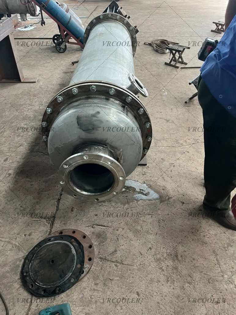
A horizontal shell-and-tube total condenser was selected. The acrolein-rich overhead vapor entered the shell through a generously sized nozzle and low-resistance inlet zone, while cooling water passed through straight tubes. This allocation gave the vapor a broad flow area and allowed the water side to be cleaned without exposing the shell-side process surface. The bundle arrangement limited unsupported vibration spans and distributed coolant to prevent isolated low-flow tubes. Thermal expansion was checked for normal operation and rapid utility changes.
The shell was installed with a continuous fall toward the condensate nozzle. Baffle cuts and spacing were chosen to support vapor distribution and heat transfer without forming pockets of liquid. The condensate outlet connected directly to a closed receiver, which supplied reflux to the column and transferred net product onward. A separate high-point vent carried non-condensable gas to the facility’s closed treatment system. No normal atmospheric vent was included.
The process-wetted metallurgy was selected only after reviewing the full overhead analysis, trace acidity, water content and cleaning procedure. Stainless pressure parts were used in the representative design, but the grade and gasket compound were confirmed through project-specific compatibility documentation. Particular attention was paid to weld finish, tube-to-tubesheet joints, gasket confinement and the removal of fabrication residues. The completed unit underwent material verification, dimensional inspection, weld examination, pressure testing and a sensitive leak test appropriate for toxic service.
The control strategy maintained a stable column-top pressure by regulating cooling-water flow within a defined operating window. A minimum flow protected water-side distribution, while the high-pressure response initiated protective action if cooling performance was lost. Temperatures were measured at the vapor inlet, condensate outlet and both cooling-water connections. The operating team also tracked column pressure and condenser temperature approach, allowing gradual fouling to be distinguished from sudden utility failure.
Because of the polymerization hazard, the operating procedure specified the approved stabilization condition, allowable temperature limits, purge sequence and maximum duration for stagnant liquid. These values came from the process chemistry authority rather than from the exchanger manufacturer. The condenser and outlet piping were drained during a controlled shutdown, and any extended outage required a defined clearing and preservation procedure. The emergency response was linked to the plant’s closed containment and abatement systems.
During commissioning, coolant circulation and instrumentation were proven before acrolein-containing vapor entered the exchanger. The system atmosphere was prepared and verified under the approved start-up procedure. Vapor load was then increased gradually while column pressure, condensate temperature, receiver level, vent behavior and coolant temperature rise were observed. This staged approach confirmed that condensation was occurring over the expected area and that the condensate drained without flooding the vapor inlet zone.
At design throughput, the representative condenser removed the required heat while maintaining the targeted column pressure and a condensate temperature close to 40°C. The cooling-water rise agreed with the thermal balance, and the vent load remained within the capacity of the closed treatment system. More importantly, operation remained stable during reduced throughput and normal changes in cooling-water temperature. The low vapor-side pressure loss protected column performance, while the sloped and drainable construction minimized retained process liquid.
The case demonstrates why an acrolein overhead condenser should not be purchased by heat duty alone. A unit with sufficient nominal surface area can still be unsuitable if it creates too much pressure drop, traps condensate, provides no effective vent for non-condensables or exposes the process to uncontrolled cold surfaces. The best solution connects thermal rating, mechanical design, chemistry control, instrumentation, relief protection and plant operating procedures from the beginning.
A properly engineered shell-and-tube condenser supports both product recovery and safe distillation. It converts the column overhead into a manageable liquid stream, supplies reliable reflux, stabilizes the separation pressure and directs residual vapor to a controlled destination. When the exchanger is designed for the real mixture, verified utility conditions and documented acrolein handling strategy, it becomes a dependable part of the process rather than a hidden limitation on capacity or safety.
Every acrolein project still requires its own process simulation, reaction-hazard review, materials assessment, relief study and operating procedure. The representative conditions above illustrate an engineering method and are not a substitute for project data. Final duty, area, configuration, metallurgy, inhibitor conditions, controls and safeguards must be approved by the responsible process, mechanical and safety specialists for the specific installation.