
A regenerant vaporizer is a specialized heat exchanger used in refinery regeneration systems to convert a liquid regenerant into vapor before it enters a superheater and passes through an adsorbent dryer. The hot vapor removes water and other retained contaminants from the adsorbent bed, allowing the dryer to return to service for another adsorption cycle. Because dryer performance depends on the condition of this vapor, the vaporizer must provide stable, repeatable evaporation without sending liquid into the downstream superheater.
This duty is found in refinery and petrochemical units that use molecular-sieve or similar adsorption systems to dry feed streams, recycle gas, hydrogen-rich gas or light hydrocarbons. Light hydrocarbon liquid from the process may be circulated as the regenerant. The liquid is heated and vaporized, superheated to the regeneration temperature, passed through the isolated dryer bed and then cooled and condensed for recovery. The regenerant vaporizer is therefore a central part of a closed regeneration loop rather than an independent utility exchanger.
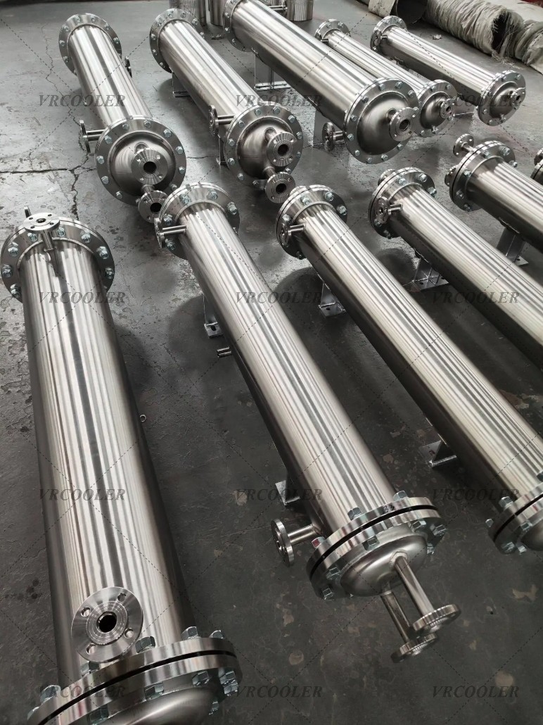
Although a conventional kettle reboiler can vaporize a liquid, refinery regenerant service often requires a more specialized construction. High process pressure, cyclic operation, compact plot space, thermal expansion, liquid-level sensitivity and the need for clean vapor generation can make a vertical bayonet-type shell-and-tube exchanger the preferred arrangement. A bayonet bundle uses concentric tubes so the heating medium travels through an inner passage and returns through the annular space. The process liquid surrounds the heated elements on the shell side and vapor separates above the controlled liquid level.
The bayonet arrangement offers several practical advantages. Each element can accommodate differential expansion more readily than a long, rigid straight-tube bundle. The exchanger can be installed vertically, which supports natural vapor disengagement and provides a compact footprint. Heating-medium distribution can be arranged so that each bayonet receives a controlled share of the flow. The construction is also suitable for high-pressure refinery service when the tubes, tubesheet, shell, closures and welded joints are engineered as a complete pressure system.
The term shell-and-tube remains appropriate because the exchanger has a pressure shell, tubesheet and tubular heat-transfer elements, but its internal flow path differs from that of a standard fixed-tubesheet exchanger. Treating it as an ordinary two-pass heater can lead to incorrect pressure-drop calculations, poor steam distribution and inadequate condensate drainage. The thermal model must represent flow through the inner tube, reversal at the closed end, return through the annulus and heat transfer through the outer tube wall to the boiling regenerant.
The process begins with a defined mass of liquid regenerant entering the vaporizer. Its composition may include several hydrocarbons rather than a single pure component. As the liquid heats, the lighter components begin to boil first and the temperature may rise along a multicomponent vaporization curve. The exchanger must therefore be rated from a full composition and vapor-liquid-equilibrium model. Selecting an area from a single normal boiling point can understate the required duty and may produce vapor with the wrong composition.
The total thermal load includes sensible heating from the inlet temperature to the bubble point, latent heat for vaporization and any intentional vapor superheat developed inside the exchanger. In many systems, the vaporizer is expected to produce essentially complete vaporization while a separate regenerant superheater supplies the larger temperature increase needed for dryer regeneration. This separation keeps boiling control inside the vaporizer and gives the downstream heater a predictable vapor feed. It also reduces the risk of operating an electric or fired superheater with liquid droplets present.
Liquid carryover is one of the most important design concerns. Droplets leaving the vaporizer can strike hot superheater surfaces, create unstable temperature control, accelerate coking and prevent the dryer from receiving a uniform gas stream. Carryover can result from excessive shell-side level, inadequate disengagement space, high vapor velocity, foaming, sudden pressure changes or poor inlet distribution. The upper shell should provide sufficient vapor space, and an appropriate disengagement or entrainment-separation device may be required when the process tendency justifies it.
The vapor outlet nozzle must be sized for the maximum expected volume, not merely the normal mass flow. The design case should include minimum operating pressure, maximum vapor rate and any start-up condition that produces a lower-density stream. High outlet velocity can entrain liquid even when the normal shell level is correct. The connected piping should rise and drain in a way that prevents liquid pockets from being swept toward the superheater during a flow change.
Level control is the defining operating variable in many vertical regenerant vaporizers. The normal level must keep the effective heating surface wetted while preserving enough disengagement volume above the boiling zone. If the level falls too low, parts of the bayonet surface may become dry, increasing wall temperature and encouraging deposit formation. If the level rises too high, liquid carryover becomes likely. A wide-range level measurement and independent protective switches are often justified because density changes and boiling turbulence can make a single reading unreliable.
The liquid-feed control valve may regulate shell level, while vapor flow is determined by regeneration demand and heat input. In other systems, feed flow is set by the regeneration sequence and steam flow is adjusted to maintain level or outlet condition. The final control philosophy should reflect how the dryer cycle is initiated, how the regenerant loop is pressurized and where excess liquid returns. Control valves must have sufficient rangeability for both warm-up and full vaporization without creating rapid oscillation.
Heating steam is commonly used because it provides a nearly constant condensing temperature and a high heat-transfer coefficient. Steam enters the bayonet elements, releases latent heat and leaves as condensate. Stable performance depends on complete condensate drainage. If condensate backs up inside the bayonets, part of the surface becomes flooded with relatively cool liquid, the effective temperature difference changes and vaporization rate can fall. A properly sized steam trap or condensate-control system must handle start-up air, normal condensate and transient loads without allowing live steam to bypass.
Steam pressure determines the maximum tube-wall temperature as well as the available temperature driving force. Increasing steam pressure can restore duty when the exchanger is fouled, but it may expose the regenerant to an unnecessarily high film temperature and accelerate coking or degradation. The normal heating pressure should therefore be selected from the process boiling curve and required approach, while the design pressure should cover the maximum utility source and credible control-valve failure case.
The vaporizer may also use another hot process stream or heat-transfer fluid, but the utility must remain controllable throughout the regeneration cycle. A process stream with a changing inlet temperature can make vapor production unstable. Thermal-oil service introduces different velocity, fouling and fire-safety considerations. Regardless of the heating medium, the supplier needs inlet and outlet conditions, mass flow, physical properties, allowable pressure drop and fouling resistance for all operating cases.
Shell-side boiling performance depends on heat flux. A large calculated area does not automatically guarantee safe operation if heat is concentrated on too few elements. Excessive local heat flux can create unstable boiling, vapor blanketing and high metal temperature. A conservative design distributes heat across the bayonets and checks the maximum heat flux at start-up, normal duty and low liquid level. The bundle layout should allow vapor to rise without becoming trapped between closely spaced elements.
The regenerant’s fouling and coking tendency must be evaluated at the tube wall rather than only at the bulk temperature. Trace heavy hydrocarbons, gums, corrosion products or contaminants released during dryer regeneration can accumulate in the loop. Repeated heating cycles may gradually form a deposit on the outer bayonet surface. That deposit raises wall temperature and reduces vaporization capacity. A realistic fouling basis, cleanability plan and performance-monitoring method should be agreed before fabrication.
Material selection begins with the complete regenerant analysis and all credible contaminants. A nominally clean light-hydrocarbon stream may also contain water, sulfur compounds, chlorides, organic acids or treatment chemicals during different phases of operation. In units that use chloride-containing chemistry, the combination of water and chlorides during start-up or shutdown may be more corrosive than the normal dry process. The materials review should cover operating, steaming, washing, preservation and upset conditions.
Carbon steel may be suitable for some regenerant services, while low-alloy steels, stainless steels, nickel alloys or clad construction may be required for others. The most expensive alloy is not automatically the best answer. Strength at design temperature, resistance to the actual corrosion mechanism, weldability, heat-treatment requirements and compatibility between shell, tubes, tubesheet and weld overlay all matter. The process licensor’s material specification and the refinery corrosion study should take precedence over a generic material recommendation.
When dissimilar materials are used, differential expansion and fabrication sequence require careful analysis. A clad tubesheet can provide corrosion resistance at the wetted surface while retaining a structural base material, but tube-to-tubesheet welding must preserve the corrosion barrier. Low-alloy components may require controlled preheat and post-weld heat treatment. Austenitic alloys need clean fabrication practices that prevent carbon-steel contamination. Every change of material affects welding procedures, nondestructive examination and repair planning.
The bayonet elements are mechanically more complex than ordinary straight tubes. Concentricity controls the annular flow area and therefore the heating-medium distribution. The closed end must withstand pressure and repeated thermal cycling. Supports must prevent vibration and contact between neighboring elements without blocking shell-side vapor flow. Dimensional tolerances influence both thermal performance and assembly, so the manufacturing inspection plan should include measurements specific to the bayonet geometry.
The tubesheet is a critical component because it separates the high-pressure process and utility circuits while supporting the entire element bundle. Its design should consider pressure differential in every operating state, including when one side is depressurized for maintenance. Ligament efficiency, thermal gradient, gasket loading and nozzle forces can govern thickness. If the exchanger is designed to an international pressure-vessel code with refinery heat-exchanger requirements, the mechanical calculations and fabrication records should clearly identify the chosen construction rules.
Refinery specifications commonly call for ASME pressure-vessel construction, TEMA exchanger practices and the applicable project requirements based on API 660. These documents do not replace the process licensor’s duty-specific requirements. Cyclic service, hydrogen exposure, sour-service restrictions, impact testing, post-weld heat treatment, alloy verification and special leak testing may all add obligations beyond a basic code calculation. The purchase specification should establish the governing hierarchy when documents differ.
The vaporizer must be designed for operating cycles rather than only steady-state pressure. A dryer system may alternate between adsorption, heating, hot regeneration, cooling and return to service. The vaporizer can therefore experience frequent temperature and flow changes. Fatigue screening should use the expected number and severity of cycles over the intended service life. Nozzles, tubesheet junctions, bayonet ends and supports deserve special attention because local stress can be higher than the general membrane stress.
Thermal insulation reduces heat loss and protects personnel, but it can conceal external corrosion. The shell material, coating and insulation system should reflect the outdoor or indoor environment and any risk of corrosion under insulation. Removable insulation at inspection points can simplify maintenance. Supports and lifting lugs should be designed for the operating weight, hydrotest condition, transport orientation and vertical erection method.
Process-side pressure drop includes the feed inlet, boiling region, vapor disengagement zone and outlet nozzle. Although the shell contains boiling liquid, the pressure profile still influences saturation temperature and control. Excessive pressure loss between the vaporizer and superheater can reduce vapor density and increase line velocity. The rating should include the full connected circuit rather than assigning the entire allowable pressure drop to the exchanger.
Utility-side pressure drop must include the nested bayonet passages. A small annular clearance may produce attractive velocity and heat transfer but can require excessive steam pressure or restrict condensate drainage. Maldistribution among elements can leave some bayonets steam-starved while others pass excessive flow. The inlet channel and internal distribution arrangement should be modeled so that all elements contribute to the specified duty.
Start-up is a particularly sensitive period. The shell and liquid may be cold, non-condensable gas may remain in the steam circuit and the downstream superheater may not yet be ready to accept full vapor flow. Steam should be introduced in a controlled manner, condensate drainage confirmed and liquid level established according to the approved sequence. Rapid heating can create severe differential expansion and sudden boiling. The interlocks should prevent the superheater from reaching high surface temperature before adequate dry vapor flow is proven.
Shutdown requires equal care. Residual hydrocarbon should not remain against hot surfaces without circulation. Steam isolation, depressurization, liquid draining and nitrogen purging must follow the process hazard analysis. If water washing or steaming is permitted, the material and corrosion review must cover the resulting wet environment. Connections should allow complete draining because retained water or hydrocarbon can complicate the next start-up and create corrosion in stagnant zones.
Instrumentation normally includes process inlet and vapor outlet temperatures, shell pressure, shell level, regenerant flow, heating-steam pressure and condensate temperature or flow. Differential pressure across the vapor outlet system can reveal restriction. High-high level should protect against liquid carryover, while low-low level can protect heated surfaces. A high tube-wall or vapor temperature alarm may be appropriate when coking or degradation is a concern. The exact safety instrumented functions must come from the unit hazard analysis.
Relief protection should cover blocked vapor outlet, control-valve failure, external fire, tube rupture and thermal expansion of blocked-in liquid. If high-pressure steam enters a lower-pressure process shell through a failed element, the relief system must handle the resulting mass and energy input. The reverse pressure relationship should also be considered because hydrocarbon entering the steam and condensate system may create a flammable release elsewhere. Relief discharges should go to an approved closed system.
Leak detection can include hydrocarbon monitoring in the condensate return, pressure surveillance and operating heat-balance comparison. A small element leak may initially appear as poor steam-trap performance or unexpected condensate contamination. Early detection is valuable because continued cross-leakage can damage the utility system and reduce regeneration reliability. The condensate network should be assessed to determine where contaminated condensate could travel.
Quality control begins with verified materials and qualified welding procedures. Pressure parts should have traceability appropriate to the project specification. Welds receive visual and nondestructive examination according to code, service and joint category. Tube-to-tubesheet joints may require mock-up qualification. Pressure testing proves structural integrity, while an additional sensitive leak test can be specified when the consequence of hydrocarbon entering the steam circuit is high.
Cleanliness during fabrication is important because debris left inside a bayonet passage can block steam or condensate flow. The element internals should be inspected and cleared before final closure. Process-wetted surfaces must be free from oil, scale, chloride contamination and foreign metal where the material specification requires it. Shipping closures and preservation should keep the exchanger dry and clean until installation.
A representative refinery project required a replacement regenerant vaporizer for a molecular-sieve dryer loop. The original exchanger had lost capacity gradually over several operating cycles. Operators compensated by raising heating-steam pressure, but vapor outlet stability continued to decline and the downstream superheater showed evidence of intermittent liquid carryover. The project objective was not simply to reproduce the old surface area; it was to restore reliable, controllable vapor generation within the available plot space.
To protect confidential operating information, the following values are representative and rounded. The hydrocarbon regenerant flow was approximately 2,000 kg/h, entering near 45°C. The process operated at elevated pressure, and the calculated multicomponent boiling range was approximately 105°C to 125°C. The vaporizer was required to deliver essentially dry vapor to a separate superheater. Medium-pressure saturated steam supplied the heat, and the calculated design duty was approximately 650 kW after sensible heating, vaporization and a practical thermal allowance were included.
The process simulation showed that a pure-component shortcut understated the duty because the regenerant contained a distribution of light hydrocarbons. The final rating used the full vaporization curve, physical properties for liquid and vapor phases and the maximum regeneration flow. A turndown case was also checked because the vaporizer needed stable level control during initial bed heating, when the regenerant rate was below the maximum value.
A vertical bayonet-type shell-and-tube exchanger was selected. Hydrocarbon liquid entered the shell side below the normal level, and vapor disengaged in the enlarged upper shell before leaving for the superheater. Saturated steam entered the inner passages of the bayonet elements and condensate returned through the annular passages to the outlet chamber. The exchanger geometry allowed the heating elements to accommodate repeated expansion while keeping the equipment footprint compact.
The upper shell volume was increased relative to the earlier arrangement, and vapor-outlet velocity was reduced. The inlet distributor prevented the colder feed from striking a small group of elements. Normal level covered the active heating area, while independent high-high and low-low level protection addressed carryover and dry heating. The vapor outlet line was arranged to drain back to the vaporizer rather than forming a pocket ahead of the superheater.
The materials review considered the normal dry hydrocarbon as well as traces of water, chloride-containing contaminants and the approved shutdown procedure. The selected pressure-part materials followed the unit corrosion study and licensor requirements. Critical process-wetted surfaces received the specified corrosion-resistant construction, while structural sections used materials appropriate to design temperature and required heat treatment. No material substitution was accepted without a complete welding and compatibility review.
The revised thermal design used a lower local heat flux than the existing exchanger. Additional effective surface provided duty without depending on excessive steam pressure. Annular clearances and steam distribution were checked for every bayonet, and the condensate system was sized for start-up as well as normal operation. The control valve retained authority across the regeneration cycle rather than operating nearly closed at low load and fully open at maximum duty.
Mechanical calculations included full pressure differential in both directions, thermal expansion, nozzle loads, shipping condition and the expected regeneration cycles. The bayonet closed ends and tubesheet junction received detailed stress attention. Fabrication included material identification, qualified welding, dimensional inspection of the concentric elements, code pressure testing and a project-specified leak test. Internal cleanliness was verified before the channels were closed.
During commissioning, the steam circuit was warmed and drained before hydrocarbon vaporization began. Shell level was established, and heat input was increased gradually while outlet temperature, steam condensate, vapor flow and superheater response were monitored. The high-level trip was tested under safe conditions. The operating team then confirmed that vapor entered the superheater without the temperature fluctuations previously associated with liquid droplets.
The replacement vaporizer reached the representative 650 kW duty without requiring the previous excessive steam pressure. Vapor flow remained stable during the main regeneration step and controllable during turndown. The downstream superheater received a consistently dry feed, allowing it to raise vapor temperature predictably. The project also improved maintenance planning by adding accessible inspection points and performance indicators that could identify fouling before regeneration time increased significantly.
The case demonstrates why a regenerant vaporizer should not be treated as a generic heater. Its success depends on two-phase behavior, liquid-level control, vapor disengagement, bayonet distribution, condensate drainage, metallurgy and the complete dryer sequence. A unit can have adequate theoretical surface and still fail if it carries liquid, traps condensate, develops excessive local heat flux or cannot tolerate repeated thermal cycles.
For a new refinery project or a replacement enquiry, the manufacturer should receive the full regenerant composition, normal and maximum flow, inlet temperature, operating pressure, required vapor fraction, allowable entrainment, fouling basis and permissible pressure drop. Heating-medium conditions must include normal and maximum pressure, temperature, available flow and condensate-return pressure. Mechanical information should define design conditions, materials, corrosion allowance, cyclic life, code, inspection, nozzle loads, hazardous-area requirements and maintenance constraints.
Final selection should also clarify whether the equipment is only a vaporizer or must provide superheat. Combining both duties may appear economical, but it changes wall-temperature control and operating stability. In many refinery dryer loops, a dedicated vaporizer followed by a separate superheater provides clearer phase control and better protection for the high-temperature heater. The decision must follow the process licensor’s regeneration philosophy.
A properly engineered shell-and-tube regenerant vaporizer gives the refinery a repeatable source of dry regenerant vapor, protects the downstream superheater, supports complete dryer regeneration and reduces the risk of an unscheduled unit limitation. The vertical bayonet design is especially valuable when high pressure, cyclic duty, thermal expansion and compact installation make an ordinary exchanger unsuitable. When process simulation, two-phase thermal design, mechanical integrity and operating controls are developed together, the vaporizer becomes a reliable part of the regeneration system rather than a recurring bottleneck.