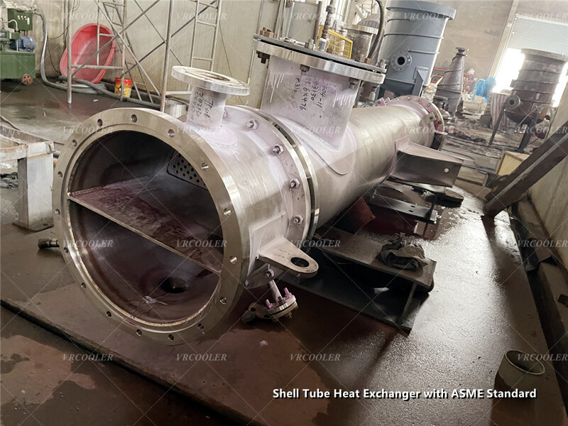
A shell-and-tube heat exchanger specified to ASME requirements combines thermal design with pressure-vessel engineering. Separate shell-side and tube-side circuits allow heat transfer between fluids while maintaining physical separation. For projects using ASME Section VIII, Division 1, Part UHX provides rules for shell-and-tube exchanger design. The applicable division and code edition should be established in the project specification.
The supplied design conditions define different pressure requirements for the two circuits, with a common design temperature range of −52°C to +210°C. The operating temperatures below are minimum/maximum values, rather than confirmed inlet and outlet temperatures.
The horizontal arrangement incorporates a baffled tube bundle. The drawing specifies 408 tubes with a 19.05 mm outside diameter, 2.11 mm minimum wall thickness and 6,500 mm length. These dimensions provide a basis for detailed thermal and mechanical assessment; cooling or heating capacity still depends on the fluids, flow rates, actual inlet and outlet conditions, and fouling allowances.
The shell-side vacuum condition requires an external-pressure assessment as well as the internal-pressure calculation. Tubes, tubesheets and their joints also need evaluation under the applicable shell-side and tube-side pressure combinations. Startup, shutdown and testing conditions can produce loads different from normal operation, so the design cannot rely only on the difference between the two listed operating pressures.
The −52°C lower design limit makes low-temperature material suitability an important selection criterion. Material grade, thickness, welding details and applicable toughness requirements need review alongside corrosion resistance and strength at +210°C. The listed hydrotest temperature range of 5–40°C describes test conditions; it does not specify the required test pressure.
Installation and maintenance provisions are also visible in the arrangement. Fixed and sliding saddle supports accommodate vessel positioning and longitudinal thermal movement. The drawing reserves 8,000 mm of maintenance clearance, which should be preserved in the installation layout. Access to flanged connections, lifting points and removable components supports future inspection and servicing.
ASME construction requires an appropriate quality-control framework covering materials, fabrication, inspection and testing. Where ASME Certification Mark application with the U designator is required, the work must be performed within an appropriately authorized manufacturer’s scope, with authorized inspection and the applicable Manufacturer’s Data Report. Certification and marking requirements should be clearly included in the purchase specification.
For a Vrcoolertech shell-and-tube heat exchanger enquiry, provide fluid properties, flow rates, required heat duty, inlet and outlet temperatures, allowable pressure drops and corrosion allowances. Include the mechanical design conditions, installation constraints and required ASME certification scope. Together, these inputs support selection of the exchanger arrangement, materials and documentation package.