
A chiller tube bundle provides the heat transfer surface between the circulating water and refrigerant. In the evaporator arrangement shown in the reference drawing, water flows through the shell while refrigerant passes inside the tubes. Heat transfers through the tube walls to the evaporating refrigerant, cooling the water while keeping the two fluids separated.
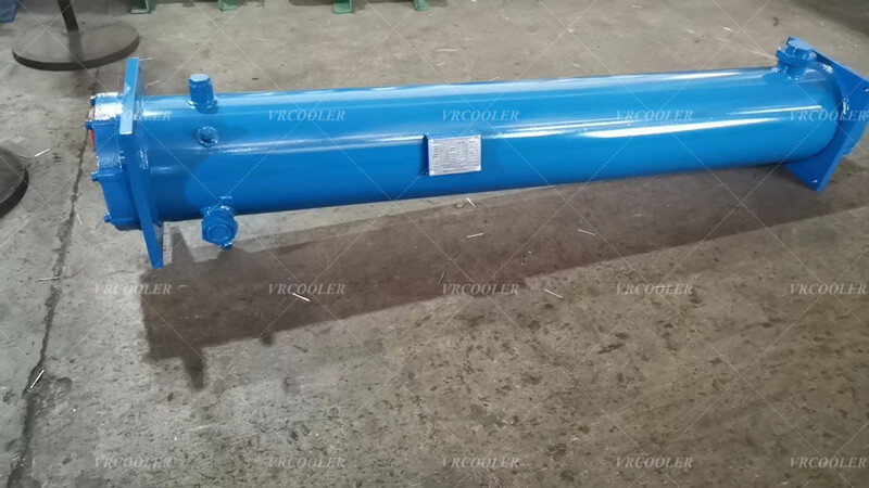
The drawing specifies a nominal heat exchange duty of 210 kW with one shell pass and two tube passes. The listed design pressures are 0.8 MPa on the water side and 1.8 MPa on the refrigerant side. These requirements establish the starting point for the bundle design, including its pressure-containing components and flow arrangement.
Accurate manufacture requires matching the internal geometry as well as the external connections. Tube length, outside diameter, wall thickness, tube pitch, tubesheet dimensions, and support arrangement all influence fit and performance. For replacement work, sealing surfaces and pass partitions must also match the existing equipment. Original drawings should be checked against site measurements where equipment has been modified.
The nominal 210 kW rating must be tied to defined operating conditions. Water flow, entering and leaving water temperatures, refrigerant type, evaporating temperature, and outlet superheat are needed to confirm performance. Tube circuiting must provide suitable refrigerant distribution with acceptable pressure loss. Each proposed refrigerant option requires its own thermal and hydraulic assessment.
Copper tubes are widely used in chiller heat exchangers because of their heat transfer properties and manufacturability. Enhanced tube surfaces may be selected to improve heat transfer, but their geometry must suit the operating fluids and duty. Tube-to-tubesheet joints must maintain separation between the water and refrigerant circuits, with the joint method selected for the materials and pressure requirements.
Water quality has a direct effect on bundle condition. Scaling, corrosion, and unsuitable flow conditions can reduce heat transfer or damage the exchanger. In this reference arrangement, water-side deposits form on the outside of the tubes, so cleaning methods must suit shell-side access and the selected materials. Water treatment and inspection should address the cause of deterioration when a replacement is planned.
The repair scope depends on the exchanger’s construction and condition. Selective retubing, replacement of a removable bundle, or replacement of the evaporator assembly may be appropriate after assessment. Where a bundle can be withdrawn, adequate removal space is required. Dimensional inspection, pressure testing, and leak testing should verify the completed assembly before installation and commissioning.
Vrcoolertech can manufacture customized tube bundles for chiller evaporators using confirmed operating data and approved fabrication drawings. Tube quantity, dimensions, circuiting, supports, tubesheet interfaces, and connections can be matched to new equipment or a verified replacement application, with thermal performance checked at the specified design conditions.