
Hydraulic oil carries power through a machine, lubricates moving components and transports heat back through the system. When that heat accumulates faster than it can escape, oil temperature rises and viscosity changes. A shell and tube hydraulic oil cooler transfers excess heat into a separate cooling-water circuit, helping the system operate within the temperature range specified for its oil and components.
This type of cooler is a practical option for hydraulic power units, presses, injection moulding machines and other equipment with a suitable water supply. Its cylindrical construction can fit alongside a reservoir or onto a machine frame. A horizontal arrangement with mounting feet provides a straightforward base for installation, while the oil and water connections can be positioned to suit the surrounding pipework.
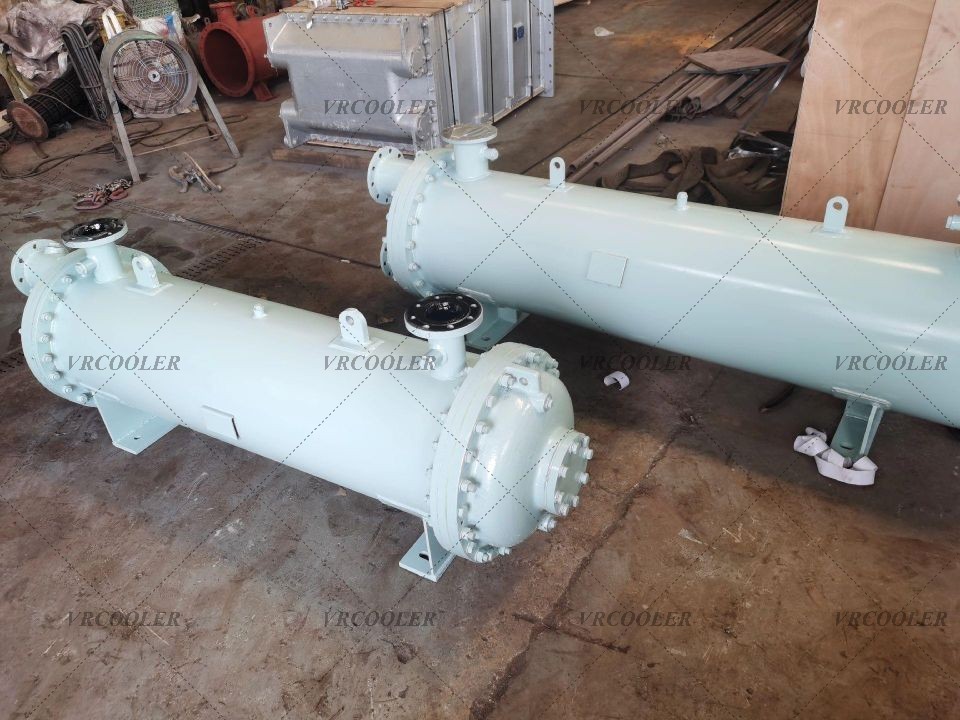
In a common arrangement, hydraulic oil flows through the shell around a bundle of tubes, and cooling water passes inside the tubes. Heat moves through the tube walls while the two fluids remain separated. Baffles guide the oil across the bundle and support the tubes. Their spacing affects both heat transfer and resistance to oil flow, so the internal arrangement needs to be selected together with the required cooling duty.
Some designs place the water inlet and outlet at the same end of the cooler. Internal partitions then direct water through the selected tube passes. This can make the external pipework easier to arrange, but the pass count must be established from the internal design. It also influences water velocity and pressure loss. Connection locations alone do not establish a cooler’s capacity.
The hydraulic motor or pump’s power rating gives context, but the cooler needs to remove the heat actually entering the oil. That heat depends on the operating cycle, pressure losses, leakage and the way the hydraulic circuit is controlled. For an existing installation, operating measurements can help establish the load. For a new machine, the system designer needs to estimate it from the intended operating conditions.
Cooling-water temperature deserves close attention. A cooler selected with cold water can lose much of its useful temperature difference when the supply becomes warmer in summer. Water flow must also remain available while other equipment is using the same utility system. Selecting against realistic water conditions makes the resulting capacity more useful than a nominal rating measured under more favourable conditions.
An illustrative design case helps explain the selection process. Consider an industrial hydraulic power unit using ISO VG 46 mineral hydraulic oil. Assume that 120 litres per minute will pass through the cooler, with oil entering at 68°C and a required outlet temperature of 50°C. Cooling water is available at 28°C, with a proposed outlet temperature of 33°C. These values are assumptions for the example; they describe a preliminary engineering study rather than a completed customer installation.
For the heat-balance calculation, assume an oil density of 850 kg/m³ and a specific heat capacity of 2.0 kJ/kg·K at the approximate operating temperature. The volumetric flow of 120 litres per minute equals 0.002 m³/s, giving an oil mass flow of 1.7 kg/s. Cooling this stream through an 18 K temperature difference requires approximately 61.2 kW of heat removal, calculated as 1.7 × 2.0 × 18. The selected oil supplier’s property data would replace these assumptions during detailed design.
The water side must absorb approximately the same heat. Using a water specific heat capacity of 4.18 kJ/kg·K and the proposed 5 K temperature rise, the required water mass flow is 61.2 ÷ (4.18 × 5), or about 2.93 kg/s. With water density approximated as 1,000 kg/m³, this corresponds to roughly 10.5 m³/h. This calculation establishes the water demand associated with the proposed temperatures and cooling duty.
The next step is to determine whether a practical tube bundle can deliver that duty within the available space and pressure-loss limits. For this example, a horizontal cooler with oil on the shell side and water inside the tubes is a suitable arrangement to evaluate. Removable water covers would provide access to the tube ends. If removal of the complete bundle is required for maintenance, that feature and the necessary withdrawal space would be included in the mechanical specification.
For an initial hydraulic assessment, assume allowable pressure losses through the cooler of 0.5 bar on the oil side at its operating viscosity and 0.3 bar on the water side at the design flow. These are illustrative targets. Tube size, pass arrangement and baffle spacing would be adjusted to balance thermal performance against those limits. The adjoining pipework and valves would have their own pressure losses, which must be included when checking the complete circuits.
Pressure drop and pressure rating describe different requirements. The pressure rating must accommodate the maximum pressure that can reach each side of the cooler, including relevant transients. A cooler installed in a return line needs assessment of return-flow peaks and backpressure. An independently pumped cooling loop has a different flow and pressure profile. Its location in the hydraulic system therefore needs to be decided before the mechanical design pressures are finalised.
Cold starting is a separate operating condition. Oil can be much more viscous before the machine warms up, increasing resistance through the cooler. Where required, a suitably designed bypass can limit excessive differential pressure, while temperature control can reduce unnecessary cooling during warm-up. Those functions need to be coordinated with the circuit so that adequate oil flow is maintained and the bypass does not prevent cooling during normal operation.
The example also shows why a summer-water check matters. Suppose the supply temperature rises from 28°C to 35°C. To remove the same 61.2 kW at approximately the same water flow, the water would need to leave at about 40°C. Keeping the oil target at 68°C in and 50°C out would then leave a smaller temperature difference for heat transfer. As a counterflow reference calculation, the log-mean temperature difference falls from approximately 28.0 K to 20.8 K.
That change would require about 34% more overall thermal conductance to maintain the same duty in the counterflow reference case. An actual multipass shell and tube selection must account for its own flow arrangement, correction factor and heat-transfer coefficients. The practical decision might be a larger bundle, a different internal arrangement or a revised cooling-water condition. A capacity commitment should cover the agreed summer condition before the cooler is manufactured.
Material selection would follow a review of the oil, cooling water and cleaning methods. Copper alloys, stainless steel or other suitable materials may be considered according to the service. Seawater introduces a different corrosion assessment from a treated freshwater loop; established oil-cooler ranges use options such as copper-nickel and titanium tube bundles for appropriate duties. The end covers and other water-contacting components also need compatible materials.
For the illustrative freshwater application, the final specification would include the water chemistry and an agreed fouling allowance. Deposits inside the tubes add thermal resistance, while restrictions can reduce water flow. Access for cleaning is therefore part of the design. The maintenance team should be able to reach the covers, isolate the water circuit and drain the unit using the intended service procedure. Pipe supports should carry external loads without forcing the cooler connections out of alignment.
Before delivery, the agreed inspection plan would cover dimensions, connection identification, material documentation and pressure and leak testing appropriate to the design. Commissioning would then establish actual oil and water flows, inlet and outlet temperatures, and pressure losses. Comparing the calculated heat removal on both sides provides a useful check, with allowance for measurement uncertainty and heat loss to the surroundings. Warm-up and sustained operation both need attention because the oil properties and control positions change as the machine reaches temperature.
The design objective in this case is to remove approximately 61 kW while meeting the specified oil outlet temperature, flow and pressure-loss limits under agreed water conditions. Actual operating results would need to be established through testing. The case demonstrates how a clear heat balance develops into a complete cooler specification, including the requirements that a dimensional drawing alone cannot provide.
For a new hydraulic power unit or an existing cooler replacement, Vrcoolertech can review the operating conditions alongside the available installation dimensions. A useful enquiry includes the oil specification, cooling duty, oil and water flows, temperature requirements, maximum pressures and allowable pressure losses. With those details established, the shell and tube hydraulic oil cooler can be developed around both the thermal task and the way the equipment will be installed and maintained.
Reference: