
Oil temperature affects how an industrial machine behaves throughout a working shift. In a hydraulic circuit, changing viscosity influences leakage, flow resistance and the response of components. In a lubrication circuit, oil must reach bearings and gears with properties suitable for the load and operating speed. A shell and tube heat exchanger removes excess heat from the circulating oil, helping both types of system maintain their intended operating conditions.
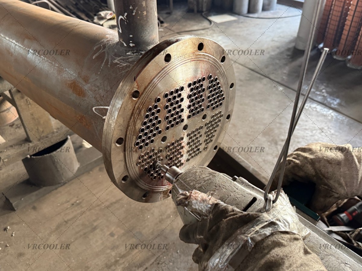
The basic arrangement is straightforward. A bundle of tubes sits inside a cylindrical shell, with oil and cooling water flowing through separate passages. Heat passes through the tube walls without the fluids mixing during normal operation. Oil commonly flows around the tubes on the shell side, while water travels inside them. Baffles can support the tubes and guide the shell-side flow across the bundle. The allocation of fluids and the internal arrangement depend on the application.
In industrial hydraulic systems, the cooler removes heat generated by losses in pumps, valves, actuators and connecting pipework. Hydraulic presses, lifting equipment and production machinery can experience changing loads and flow rates during each operating cycle. The cooler may be installed in a return line or in a separate circulation loop connected to the reservoir. Its position determines the flow conditions and pressures it must accommodate.
Return-line selection requires particular care. Flow returning from an actuator can differ from pump delivery, and short flow peaks may create more backpressure than the average operating condition suggests. An independently pumped cooling loop gives the designer more control over the flow through the exchanger. Its pump, cooler and controls still need to be matched to the reservoir heat load and the oil’s viscosity range.
Machine lubrication circuits have a different priority: maintaining the required oil supply to moving components. Gearboxes, bearing systems and other circulating lubrication installations need suitable oil temperature together with adequate flow and delivery pressure. Every component in the supply circuit consumes part of the available pressure, including the cooler, filters, valves and piping. The exchanger’s pressure loss must therefore fit within the complete lubrication-system design.
The correct oil temperature comes from the machine requirements and lubricant properties. Hydraulic oil and gearbox lubricant can have different viscosity grades, additive packages and operating limits. Even two oils with the same nominal grade can behave differently as temperature changes. Cooler selection should use the relevant fluid data at normal operation and cold start, rather than relying on a single viscosity value.
The internal construction balances heat transfer, pressure loss and maintenance access. More tube passes increase water velocity for a given flow and tube arrangement, but they also increase resistance. Baffle spacing influences how the oil crosses the bundle. Removable water covers provide access to the tube ends, while a removable bundle can offer additional maintenance options where specified. The installation needs enough clearance to use those features after the pipework is connected.
Materials are selected for both fluids and the expected service conditions. The assessment covers the tubes, shell, tube sheets, end covers and seals. Cooling-water chemistry and cleaning methods can be as important as the oil specification. A treated freshwater loop, open cooling-tower circuit and seawater supply require different corrosion assessments. The complete combination of materials must suit the service, including any dissimilar-metal connections.
An illustrative case study shows how the two applications can be handled within one manufacturing line. Assume that the line has a hydraulic power unit and a separate circulating lubrication system for a gearbox. The hydraulic circuit uses ISO VG 46 mineral oil, while the gearbox uses ISO VG 68 lubricating oil. Each oil circuit has its own reservoir and cooler, and both coolers receive water from a common utility header. All operating values in this example are design assumptions, with no claim of completed customer performance.
For the hydraulic cooler, assume an oil flow of 100 litres per minute, entering at 65°C and leaving at a target temperature of 50°C. Using an illustrative density of 850 kg/m³ and specific heat capacity of 2.0 kJ/kg·K, the mass flow is approximately 1.417 kg/s. The resulting cooling duty is 1.417 × 2.0 × 15, or 42.5 kW. This calculation defines the heat removal associated with the specified stream conditions.
For the lubrication cooler, assume a flow of 60 litres per minute, with oil entering at 60°C and leaving at 45°C. Using the same density and specific heat assumptions for this preliminary calculation gives a mass flow of 0.85 kg/s and a cooling duty of 25.5 kW. Detailed selection would use the actual properties of each lubricant. The two outlet temperatures are application assumptions that would need confirmation against the equipment manufacturer’s requirements.
The combined water-side heat load is therefore 68 kW. If cooling water enters both exchangers at 30°C and leaves at 35°C, the hydraulic cooler requires approximately 7.3 m³/h and the lubrication cooler approximately 4.4 m³/h. These flows follow from the individual duties using a water specific heat capacity of 4.18 kJ/kg·K and density approximated as 1,000 kg/m³. The utility header must supply about 11.7 m³/h when both circuits operate at the stated duty.
Each water branch would have a means of setting and checking its flow. This matters because the two exchangers and their branch pipework can have different resistances. Adequate total flow at the header does not establish how much reaches each cooler. Separate temperature measurements and accessible flow-checking points would make balancing and later troubleshooting easier.
The smaller lubrication duty would still need its own thermal selection. Its target oil outlet temperature is 45°C, only 15 K above the proposed entering water temperature. The hydraulic cooler has a 20 K difference between those corresponding temperatures. Consequently, the ratio of their heat loads cannot be used directly to determine the ratio of their required heat-transfer areas. Oil properties, internal flow conditions and temperature differences all contribute to the selection.
Pressure-loss limits would be allocated individually. On the hydraulic side, the design would check the flow that can actually pass through the cooler during the operating cycle. On the lubrication side, it would confirm that the required pressure remains available at the machine after losses through the cooler and other components. Both assessments would include cold oil, when viscosity can be substantially higher. Maximum working pressure, design pressure and allowable pressure drop would be stated separately in the equipment specification.
Temperature regulation would also be independent for the two circuits. Depending on the system design, a controlled water valve or an oil bypass arrangement could regulate cooling during changing loads and warm-up. The controls would preserve the required oil circulation while bringing each circuit towards its own temperature target. Any differential-pressure bypass would be coordinated with that arrangement so its operation and effect on cooling are understood.
The shared water supply would be assessed at its warmest expected condition. If water reaches the coolers above the assumed 30°C, less temperature difference is available to transfer the heat. The lubrication circuit may be particularly sensitive because of its lower oil outlet target. The final exchanger ratings would therefore include the agreed maximum entering-water temperature, available flow and fouling allowance. This establishes a useful operating envelope for the equipment.
The maintenance plan would address fluid condition as well as cleaning. Water-side deposits can reduce heat transfer, while contamination or a developing restriction can affect circulation. A tube leak can allow cross-contamination according to the pressure difference between the fluids. That pressure relationship can change when an oil pump stops while water pressure remains present. Isolation arrangements, inspection and appropriate oil-condition monitoring should be considered as part of the complete system.
For this illustrative installation, the coolers would be mounted with accessible connections, supported pipework and sufficient clearance for the agreed service procedure. Inspection before delivery would cover the specified dimensions, materials and pressure and leak tests. During commissioning, measurements would establish the oil and water flows, temperatures and pressure losses. The lubrication circuit would also be checked for adequate delivery to the machine throughout warm-up and normal operation.
The intended result is controlled cooling of both oil circuits while maintaining their required flow and pressure conditions. The hydraulic unit needs approximately 42.5 kW of heat removal at its stated design point, and the lubrication circuit needs approximately 25.5 kW. Keeping the two oil systems separate allows each cooler and control arrangement to be selected for its own service while sharing the available water infrastructure. Actual performance would be established through commissioning and operating measurements.
Vrcooler can review shell and tube heat exchanger requirements for industrial hydraulic systems and machine lubrication circuits using the operating data and installation constraints. For a replacement, connection positions, mounting dimensions and service clearance are important alongside thermal duty. For a new system, establishing the oil properties, load, water conditions and pressure-loss budget early gives the cooler design a clear basis and helps it fit the way the machine will operate.
Reference: