
A replacement tube bundle for a lube oil cooler provides a practical way to restore heat-transfer performance without replacing the complete shell-and-tube heat exchanger. The new bundle is manufactured to fit the existing shell, channel and connection arrangement while matching the original thermal duty, pressure limits and hydraulic performance.
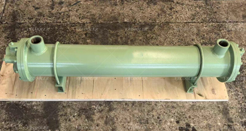
This lube oil cooler uses a horizontal shell-and-tube arrangement. Hot lubricating oil flows through the shell side, while cooling water circulates inside the tubes. The oil transfers heat through the tube walls to the water, allowing the cooled lubricant to return to the machinery at a safe operating temperature.
According to the technical conditions, the shell-side oil flow is approximately 120,000 lb/h, or 54,400 kg/h. The oil enters the cooler at about 157.5°F and leaves at approximately 139.1°F, corresponding to an inlet temperature of around 69.7°C and an outlet temperature of 59.5°C.
The tube side handles approximately 130,000 lb/h, or 59,000 kg/h, of cooling water. The water enters at about 93°F and leaves at approximately 101°F, equivalent to a temperature rise from around 33.9°C to 38.3°C. The calculated heat-transfer duty is approximately 1.04 million Btu/h, or about 304 kW.
Maintaining the specified oil outlet temperature is essential for reliable lubrication. Excessively hot oil loses viscosity and may be unable to maintain a strong lubricating film between bearings, gears and other moving components. This can increase friction, accelerate wear and shorten the service life of both the lubricant and the machinery.
The replacement assembly uses a U-tube bundle. Each tube is bent at one end, allowing both tube ends to be fixed into a common tubesheet. This design accommodates differential thermal expansion between the tubes and shell without requiring a separate expansion joint. It also eliminates one tubesheet and reduces the number of potential tube-to-tubesheet leakage points.
The bundle contains approximately 104 tubes with an outside diameter of 0.625 inch and an average wall thickness of about 0.065 inch. The effective tube length is approximately 7 ft. The tubes are arranged on a 0.75-inch triangular pitch, which provides a compact heat-transfer surface and promotes turbulence in the oil flowing around the bundle.
Low-fin carbon-steel tubes are specified for the heat-transfer surface. The external fins increase the surface area available on the oil side, where the heat-transfer coefficient is lower because lubricating oil is more viscous than cooling water. This design provides greater thermal performance than a smooth-tube bundle of similar size.
The cooler provides an effective heat-transfer area of approximately 884 ft², equivalent to about 82 m². The large surface area allows the bundle to remove the required heat while maintaining a reasonable oil-side pressure drop. The original thermal selection also includes an overdesign allowance of approximately 32.5%, helping compensate for normal fouling and changing operating conditions.
Single-segmental baffles direct the oil repeatedly across the tubes. The specified baffle cut is approximately 35.1%, with a center-to-center spacing of about 4.9 inches. This arrangement supports the tubes, reduces vibration and increases oil turbulence, improving heat transfer across the bundle.
Baffle design is especially important in an oil cooler. If the spacing is too wide, the oil velocity may be insufficient and stagnant zones can develop. If the baffles are positioned too closely, shell-side pressure loss may become excessive. The replacement bundle should reproduce the original baffle geometry unless a complete thermal and mechanical redesign confirms that a different arrangement is preferable.
The calculated oil-side pressure drop is approximately 8.3 psi, remaining below the allowable value of 10 psi. The cooling-water pressure drop is approximately 0.63 psi, compared with an allowable value of about 5 psi. Matching these hydraulic conditions helps ensure that the existing oil and water pumps can continue operating without modification.
The cooler uses a single shell-side pass and two tube-side passes. Dividing the water circuit into two passes increases the velocity inside the tubes, improving heat transfer and helping limit deposit formation. The pass arrangement must be reproduced accurately in the replacement bundle and channel partition to prevent internal bypassing.
The tube-side water passages require regular inspection because scale, sediment and biological deposits can reduce cooling capacity. U-tubes cannot normally be cleaned mechanically through their full length with a straight rod, so water quality control and chemical or circulation cleaning may be required. The cooling-water analysis should be reviewed before confirming the final tube material.
Carbon steel is economical and mechanically strong when the cooling water is properly treated. If the existing bundle has suffered repeated corrosion or tube leakage, stainless steel, copper-nickel or another corrosion-resistant material may be considered. Changing tube material, however, affects thermal conductivity, galvanic compatibility, wall thickness and bundle performance, so it should be supported by revised engineering calculations.
The shell has an internal diameter of approximately 13.4 inches. The replacement bundle must match the original tubesheet diameter, sealing face, bolt pattern, bundle length, pass-partition arrangement and insertion clearance. Accurate dimensional control is critical because even a small difference can prevent the bundle from fitting the existing shell or create excessive bypass between the bundle and shell wall.
The documented bundle weight is approximately 664 lb, or about 301 kg. Suitable lifting points, supports and handling procedures should be prepared before removing the old bundle and inserting the replacement. The withdrawal area must also be long enough to accommodate the complete U-tube assembly.
Before manufacturing, the condition of the existing shell, channel cover, gasket surfaces and internal supports should be inspected. Installing a new bundle into a damaged or heavily corroded shell may not provide a reliable long-term solution. The alignment of the shell, nozzles and supporting structure should also be checked.
The tubes, U-bends and tube-to-tubesheet joints must undergo suitable inspection and pressure testing before delivery. Dimensional verification should confirm the tubesheet, baffle positions, bundle length and connection orientation. Cleanliness is particularly important because welding residue, metal particles and moisture must not enter the lubrication circuit during commissioning.
Replacing only the tube bundle reduces cost and shortens the equipment shutdown compared with installing a complete new cooler. It also allows the existing shell, foundations and external piping to remain in place. When the replacement is accurately engineered, the restored cooler can provide the original heat-transfer capacity while extending the service life of the lubrication system.
Vrcoolertech can manufacture customized replacement tube bundles for turbine, compressor, gearbox, generator and industrial lube oil coolers. The U-tube configuration, tube material, fin type, tubesheet, baffles and overall dimensions can be reproduced from the original drawing and verified against the required operating conditions.
This replacement bundle is designed to provide approximately 304 kW of heat removal, cooling the lubricating oil from around 69.7°C to 59.5°C with cooling water entering at approximately 33.9°C. Accurate dimensional matching, controlled tube expansion, reliable pressure testing and appropriate material selection are essential to restoring the cooler’s performance safely.