
An exhaust gas heat exchanger can recover high-temperature energy from a syngas engine and use it to generate low-pressure saturated steam. Instead of releasing exhaust gas at approximately 500°C directly to the atmosphere, a shell-and-tube exhaust gas heat exchanger transfers part of this energy to treated feedwater. The proposed system is intended to produce approximately 150 kg/h of saturated steam at around 105°C.
The appropriate equipment is essentially a compact waste-heat steam generator based on a shell-and-tube or fire-tube construction. Hot engine exhaust normally flows through the tubes, while water and steam occupy the shell side. This arrangement keeps the dirty exhaust inside accessible tubes, making inspection and mechanical cleaning easier. It also provides a stable water volume around the tubes for steam generation.
The stated steam pressure requires clarification. Saturated steam at 105°C corresponds to approximately 1.2 bar absolute. If the required pressure is 1.2 bar gauge, the absolute pressure would be approximately 2.2 bar, and the corresponding saturation temperature would be close to 123°C rather than 105°C. Final mechanical and thermal calculations must therefore confirm whether the pressure is expressed as absolute or gauge pressure.
Producing 150 kg/h of saturated steam requires a steam flow of approximately 0.0417 kg/s. The required heat duty depends strongly on the feedwater inlet temperature. If feedwater enters at approximately 20°C, heating it to saturation and completely evaporating it at 105°C requires roughly 108 kW. With warm returned condensate or preheated feedwater entering at approximately 80°C, the required duty falls to about 98 kW. A practical preliminary design duty would therefore be approximately 100–110 kW before allowing for external heat losses and operating margin.
This demand is relatively high for the exhaust of a 100 kWe gas engine. The electrical rating alone does not confirm the recoverable exhaust heat. Depending on the engine’s electrical efficiency, air-fuel ratio and cooling-system heat distribution, the exhaust may contain approximately 60–110 kW of usable thermal energy. Generating 150 kg/h of steam may therefore be possible only if the engine provides sufficient exhaust mass flow and if a large proportion of the available exhaust heat can be recovered.
The 500°C exhaust temperature is favorable, but temperature alone is not enough to size the exchanger. The exhaust-gas mass flow rate, composition and permitted outlet temperature are essential. The available duty can be calculated from the exhaust mass flow, average specific heat and temperature reduction through the exchanger. The allowable exhaust outlet temperature must remain high enough to avoid excessive condensation, corrosion and loss of natural chimney draft.
If the engine produces only 80 kW of recoverable exhaust heat, the corresponding steam production would be closer to 110–120 kg/h, depending on feedwater temperature and system losses. If at least 105–115 kW is available under continuous operating conditions, the target of approximately 150 kg/h becomes more realistic. The engine manufacturer’s exhaust heat rejection data should therefore be used for final verification.
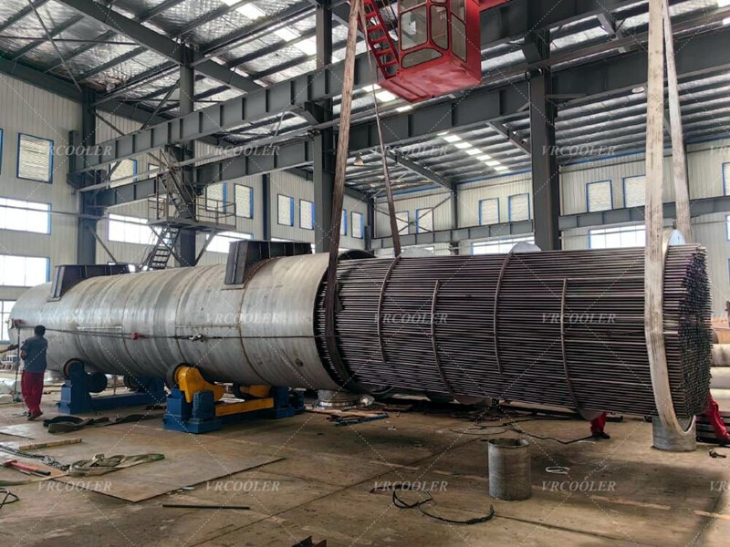
The exchanger should be designed with exhaust gas inside the tubes and boiling water on the shell side. Hot gas enters a refractory-lined or heat-resistant inlet chamber before being distributed across the tube bundle. As the gas flows through the tubes, it transfers sensible heat to the surrounding water. Steam rises into the upper disengagement space and leaves through a steam outlet connection, while feedwater is introduced through a controlled inlet.
Stable water-level control is critical. If the water level falls too low, tubes exposed above the water surface may overheat and suffer rapid damage. If the water level is too high, water droplets may be carried into the steam line. The system should incorporate automatic feedwater control, independent low-water protection, a high-water alarm, pressure monitoring, temperature measurement, a safety relief valve and a blowdown connection.
The exhaust-side pressure drop must be kept within the engine manufacturer’s permitted backpressure. Excessive resistance can reduce engine output, increase fuel consumption and raise exhaust temperature. The final design should account for pressure losses through the inlet duct, heat-exchanger tubes, return chamber, outlet duct, silencer and chimney.
Gas velocity through the tubes must balance heat transfer, fouling and pressure drop. High velocity improves the gas-side heat-transfer coefficient but increases engine backpressure and may cause erosion if the exhaust contains particles. Low velocity reduces pressure loss but requires a larger tube bundle and can encourage deposits. Removable access covers and cleaning ports are advisable, particularly where syngas quality may vary.
Material selection depends on the composition and cleanliness of the syngas engine exhaust. Stainless steel 316L can be considered as a practical baseline for the tubes and exhaust-contact surfaces when moderate corrosion resistance is required. However, material selection cannot be based on exhaust temperature alone. Syngas may contain sulfur compounds, chlorides, tars, particles or other contaminants derived from the original fuel and gas-cleaning process.
The region nearest the 500°C exhaust inlet experiences the highest metal temperature and thermal stress. Depending on the calculated tube-wall temperature and exhaust composition, a higher-temperature stainless steel such as 310S or another heat-resistant alloy may be considered for the inlet chamber or first tube section. The tubesheet design must also accommodate the large thermal difference between the entering exhaust gas and the boiling water.
Although the incoming gas is hot, corrosion risk often becomes greater at the cold end of the exchanger. If the tube-wall temperature falls below the water or acid dew point of the exhaust, corrosive condensate can form. This is particularly important when the syngas contains sulfur compounds. The exhaust-gas composition, sulfur concentration and expected acid dew point should be established before setting the minimum gas outlet temperature.
The exchanger may use a single-pass or multi-pass exhaust arrangement. A multi-pass design can increase gas velocity and heat recovery within a compact shell, but it also creates additional pressure drop. For a small gas engine, a low-pressure-drop single-pass or carefully designed two-pass configuration may provide a better compromise.
The final system should be insulated to reduce surface heat loss and protect personnel. Thermal expansion between the hot exhaust connections and the exchanger should be accommodated using flexible joints or expansion compensators. A bypass damper is also useful because it allows the engine to continue operating when the steam generator is isolated, warming up or undergoing maintenance.
Feedwater quality is equally important. Scale on the water side creates an insulating layer, raises tube-wall temperature and reduces steam-generating capacity. Treated and deaerated feedwater should be used wherever possible, with regular blowdown to control dissolved solids. A proper steam separator may be included when the downstream process requires dry saturated steam.
For preliminary selection, the exhaust gas heat exchanger should be rated for approximately 110 kW of useful steam-generating capacity, subject to confirmation of the engine’s exhaust heat availability. The target steam production is 150 kg/h at 105°C and approximately 1.2 bar absolute. A corrosion-resistant shell-and-tube construction with stainless steel exhaust-contact components, low engine-side pressure drop, automatic water-level control and complete pressure-safety protection is recommended.
Final sizing requires the exhaust mass flow, minimum and maximum engine load, allowable backpressure, target exhaust outlet temperature, detailed gas composition, feedwater inlet temperature, required steam pressure basis and applicable pressure-vessel code. These values will determine whether the full 150 kg/h steam production can be achieved continuously from the available 100 kWe engine exhaust.