
A shell-and-tube atmospheric condenser can be designed for installation inside an engine room to condense exhaust steam and collect the resulting condensate. Based on the stated steam flow of 90,000 kg/h, however, this is a large condenser with a preliminary heat-rejection duty of approximately 60 MW. The proposed cooling-water flow of 1,180 m³/h is insufficient to absorb this duty while keeping the outlet temperature below 40°C.
The exhaust steam enters the shell side close to atmospheric saturation conditions. At approximately 1 bar absolute, saturated steam has a temperature close to 100°C, a saturated-vapor enthalpy of about 2,676 kJ/kg and a saturated-liquid enthalpy of approximately 417.5 kJ/kg. The provided saturated-liquid enthalpy is therefore consistent with steam condensing near atmospheric pressure.
If the condensate must leave the condenser at 65°C, it is not only necessary to remove the latent heat of condensation but also to subcool the condensate from approximately 100°C to 65°C. Water at 65°C has an enthalpy of roughly 272 kJ/kg. The total heat removed from each kilogram of incoming saturated steam is therefore approximately 2,403 kJ/kg.
At an exhaust-steam flow of 90,000 kg/h, or 25 kg/s, the calculated condenser duty is approximately 60,000 kW. A reasonable preliminary rating is therefore about 60 MW, before applying any design margin or accounting for variations in steam pressure, steam quality and engine load.
The stated cooling-water flow is 1,180 m³/h, with water entering at 27°C and required to leave below 40°C. This provides a maximum temperature increase of 13 K. At this flow and temperature difference, the water can absorb only approximately 17.8 MW. This is less than one-third of the calculated exhaust-steam duty.
If the complete 90,000 kg/h steam flow must be condensed and the cooling-water outlet must remain at or below 40°C, the required cooling-water flow is approximately 4,000 m³/h. Allowing for thermal variation, fouling and flow-control margin, a preliminary design flow in the range of approximately 4,200–4,400 m³/h would be more practical.
If the water flow must remain at 1,180 m³/h, the cooling-water outlet temperature would theoretically rise to approximately 71°C when absorbing the full 60 MW. Such a condition does not meet the specified outlet limit and may not be achievable because the decreasing temperature difference would require a much larger heat-transfer surface.
Alternatively, at 1,180 m³/h and a water temperature rise from 27°C to 40°C, the condenser could handle only about 26,000–27,000 kg/h of saturated exhaust steam, assuming condensate is cooled to 65°C. The steam flow, cooling-water flow or permitted water outlet temperature must therefore be revised before a reliable budgetary selection can be prepared.
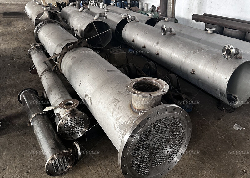
The atmospheric condenser would normally use a shell-and-tube surface-condenser arrangement. Exhaust steam enters the shell through a large steam inlet connection and flows around the outside of the tubes. Cooling water circulates inside the tubes, allowing the water circuit to operate at approximately 2 barg while the shell remains close to atmospheric pressure.
Placing cooling water inside the tubes also simplifies tube cleaning and allows corrosion-resistant tube materials to be selected according to the cooling-water quality. If treated freshwater is used, stainless steel or copper-alloy tubes may be considered depending on the complete water analysis. If the cooling medium is seawater, titanium or suitable copper-nickel tubes are generally more appropriate, while tubesheets and water boxes require compatible materials or protective cladding.
The steam inlet connection requires special attention because near-atmospheric steam occupies a very large volume. At approximately 100°C, the incoming steam flow can exceed 40 m³/s before condensation begins. The steam inlet neck, transition duct and shell entrance must therefore be designed for low velocity and low pressure loss. Excessive inlet resistance can increase engine exhaust backpressure and reduce performance.
Although the equipment is described as an atmospheric condenser rather than a vacuum condenser, the permissible shell-side pressure range must still be specified. The engine exhaust pressure, maximum allowable backpressure and condenser pressure drop are necessary for correctly sizing the inlet connection and steam passages. A small positive pressure may be required to move steam through the condenser, but it should remain within the engine manufacturer’s limit.
The condenser should include a condensate collection section beneath the main tube bundle. Subcooling the condensate to 65°C may require a dedicated section where the condensed water remains in contact with the coldest cooling-water tubes. The condensate outlet should be connected to a receiver or extraction pump selected for the available static head and operating pressure.
Cooling condensate from approximately 100°C to 65°C accounts for about 3.6 MW of the total duty. If this degree of subcooling is not required, allowing warmer condensate to leave the condenser would reduce cooling-water demand and conserve useful heat. If the condensate is returned to a boiler-feedwater system, a higher outlet temperature could improve overall plant efficiency.
Non-condensable gases must be removed continuously. Air and other gases can collect around the colder portions of the tube bundle and create a thermal resistance that sharply reduces condensation performance. Properly positioned vent connections and an air-removal arrangement are therefore required even though the condenser is not intended to operate under vacuum.
The cooling-water pressure of 2 barg is acceptable as a preliminary operating value, but the available pump head and maximum permissible pressure drop must be confirmed. A water flow near 4,000 m³/h will require large nozzles, water boxes and connecting pipes. The tube diameter, tube quantity and number of water passes must be optimized to provide adequate velocity without creating excessive pressure loss or erosion.
Installation inside an engine room introduces additional considerations. The condenser itself does not eliminate the recovered heat; it transfers approximately 60 MW from the steam into the cooling-water circuit. A cooling tower, dry cooler, seawater system or other external heat sink must then reject this energy. Heat losses from the condenser shell, hot piping and condensate equipment should also be considered in the engine-room ventilation calculation.
The shell, tube bundle, water boxes and supporting structure will be substantial for a 60 MW atmospheric condenser. Equipment access, tube-pulling clearance, floor loading, lifting arrangements and transportation restrictions must be established before deciding whether the condenser should use one large shell or several parallel modules. A modular arrangement may simplify transportation, installation and maintenance while providing partial operating redundancy.
A budgetary proposal can be developed after correcting the thermal balance and confirming the cooling-water source, water analysis, steam pressure, steam quality, allowable engine backpressure, required condensate temperature, available installation space and applicable pressure-vessel code. On the current basis, the preliminary condenser duty is approximately 60 MW, and the cooling-water flow should be increased from 1,180 m³/h to approximately 4,200 m³/h if the 27°C inlet and maximum 40°C outlet temperatures must be maintained.