
An atmospheric condenser removes latent heat from low-pressure exhaust steam and converts the vapor into reusable condensate without requiring the deep vacuum normally associated with a turbine surface condenser. Although the operating principle appears straightforward, a large steam flow creates a demanding thermal and hydraulic duty. The condenser must accept a very high volumetric vapor rate, distribute that vapor across the tube bundle, remove non-condensable gases, drain condensate without flooding the heat-transfer surface and keep the cooling-water pressure loss within the available pumping head.
A shell-and-tube surface condenser is a practical choice for this service because it keeps the exhaust steam and cooling water completely separate. Steam normally enters the shell side, where the large cross-sectional area accommodates the low-density vapor. Cooling water passes through the tubes, where its velocity, number of passes and pressure drop can be controlled. The condensate collects in the lower part of the shell and leaves through a dedicated outlet, while air and other non-condensable gases are removed from a carefully selected vent location.
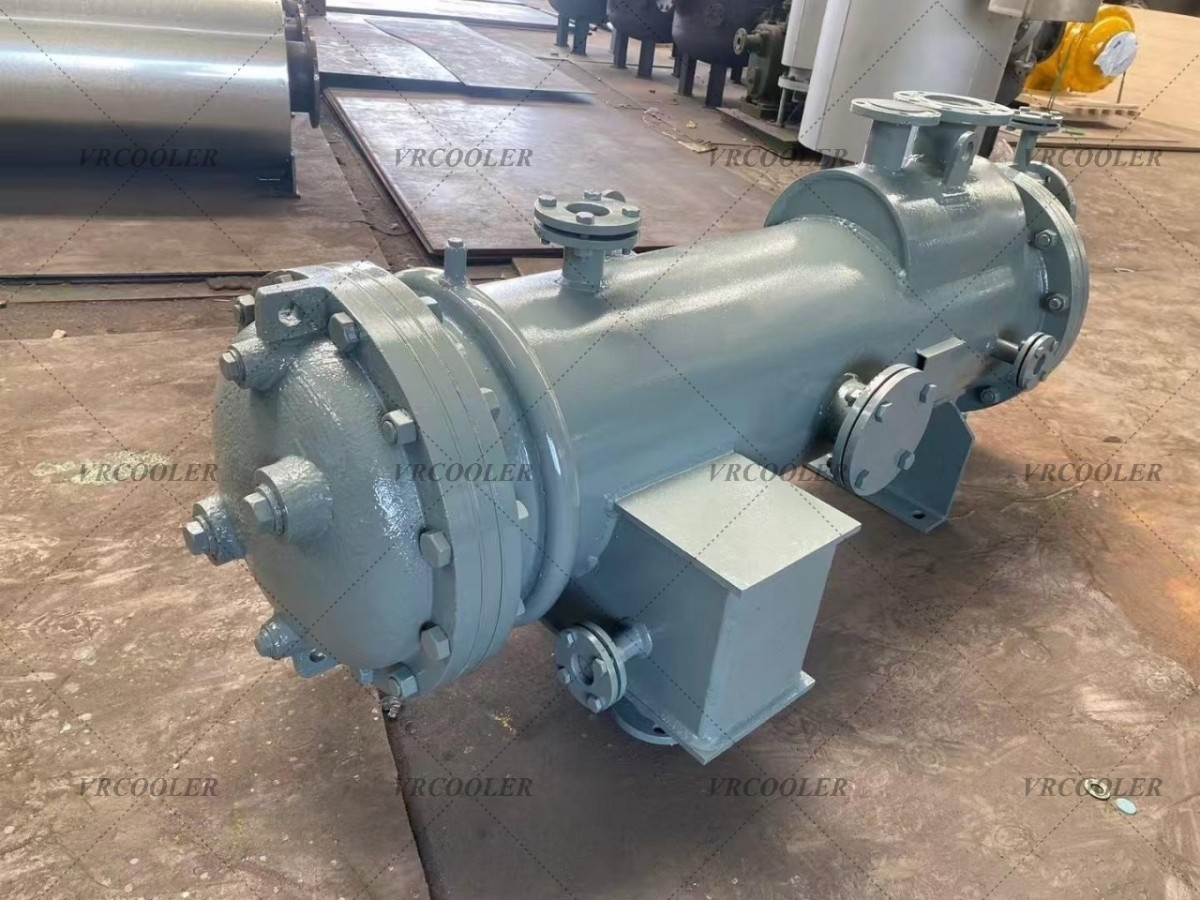
This separation is important when the condensate is returned to a boiler, hotwell, feedwater tank or process-water system. Direct-contact condensation can be compact, but it mixes the cooling water with the condensate. A surface condenser preserves condensate quality and permits the cooling-water circuit to use water that would not be acceptable as boiler feedwater. It also makes leakage easier to monitor because a change in condensate conductivity can indicate a cooling-water tube failure.
The design basis considered here describes approximately 90,000 kg/h of exhaust steam on the shell side. The supplied saturated-liquid enthalpy is 417.5 kJ/kg, which is consistent with water close to 100°C and therefore suggests condensation near atmospheric pressure. The required condensate outlet temperature is 65°C. On the tube side, the preliminary cooling-water flow is 1,180 m³/h at an inlet temperature of 27°C, with the return temperature required to remain below 40°C. Tube-side operating pressure is 2.0 barg.
These values must first be converted into a consistent heat balance. The saturated-liquid enthalpy does not represent the enthalpy of incoming dry steam. Near atmospheric pressure, dry saturated steam has a total specific enthalpy of approximately 2,676 kJ/kg, while saturated liquid is approximately 419 kJ/kg. The difference, approximately 2,257 kJ/kg, is the latent heat released during condensation. Cooling the resulting condensate from roughly 100°C to 65°C removes a further sensible load of about 146 kJ/kg.
If the exhaust is assumed to be dry saturated steam at atmospheric pressure, the total specific heat removal is therefore approximately 2,404 kJ/kg. Multiplying this value by 90,000 kg/h gives a preliminary condenser duty of about 216 million kJ/h, or approximately 60 MW. The exact result will change with actual exhaust pressure, steam quality, superheat, non-condensable content and any liquid carried into the condenser, but it will remain far above the capacity indicated by the preliminary cooling-water flow.
Water flowing at 1,180 m³/h and warming from 27°C to the maximum permitted temperature of 40°C can absorb only about 17.8 MW. This calculation uses a water heat capacity close to 4.18 kJ/kg·K and a temperature rise of 13 K. If the same flow absorbed a 60 MW duty, its theoretical temperature rise would be approximately 44 K, producing an outlet temperature near 71°C rather than below 40°C. The preliminary steam-side and water-side conditions are therefore not thermally balanced.
Maintaining a 13 K cooling-water rise at an approximately 60 MW duty would require a flow close to 4,000 m³/h, before allowance for fouling, uncertainty and design margin. Conversely, 1,180 m³/h of water limited to a 13 K rise can condense and subcool only about 26,000 to 27,000 kg/h of comparable atmospheric steam. This discrepancy is too large to resolve by changing tube material, surface area or the overall heat-transfer coefficient. At least one basic process value must be revised, or the cooling system must be expanded substantially.
The first clarification should be the absolute pressure and temperature of the steam at the condenser inlet. The word atmospheric may refer to a shell operating close to ambient pressure, a vented condensate receiver or simply a condenser that does not maintain a turbine vacuum. These are not identical conditions. Even a modest positive or negative pressure changes saturation temperature, vapor density and volumetric flow. The vendor needs the normal, minimum and maximum absolute pressure rather than a gauge-pressure description alone.
Steam quality is equally important. If the exhaust contains entrained liquid, the actual enthalpy is lower than that of dry saturated steam. The dryness fraction can be used to calculate the mixture enthalpy, but it would have to be extremely low to reconcile the stated steam flow with only 17.8 MW of cooling capacity. If the inlet is superheated, a separate desuperheating zone must be included and the duty will increase. A verified inlet enthalpy or a complete pressure-temperature-quality specification is therefore essential.
The figure of 417.5 kJ/kg should also be labelled clearly. It appears to be saturated-liquid enthalpy, not the enthalpy of the entering exhaust steam. Using it as the incoming vapor enthalpy would omit almost the entire latent heat load and produce a severely undersized condenser. The final process document should provide steam inlet enthalpy, saturation pressure, dryness fraction and required condensate outlet enthalpy on the same reference basis.
Condensate temperature deserves a separate review. Producing liquid at 65°C from steam condensing close to 100°C requires substantial subcooling. This may be intentional when the condensate enters a vented tank, because cooler liquid reduces flash steam. It may also support downstream handling or heat recovery. However, deep subcooling inside a condenser can require a flooded bundle section, create a larger surface requirement and reduce the temperature driving force near the liquid outlet. If hot condensate can be recovered at a higher temperature, separating condensation from condensate cooling may offer a better energy solution.
One arrangement is to use the main surface condenser for latent heat removal and a separate condensate cooler for controlled subcooling. This allows the condenser to drain freely and gives the liquid-cooling duty its own control loop. Another option is a divided shell or deliberately flooded subcooling zone within the same casing. The correct configuration depends on plot space, condensate system pressure, allowable flash generation, heat-recovery opportunities and the plant’s preference for equipment count.
The shell-side vapor volume determines the inlet nozzle and distribution space. At atmospheric conditions, saturated steam has a specific volume of roughly 1.67 m³/kg. A flow of 90,000 kg/h would therefore approach 150,000 m³/h before allowance for superheat or non-condensables. Such a stream cannot enter through a conventionally sized liquid nozzle without high velocity, pressure loss, vibration and uneven bundle loading. The condenser may require a very large inlet connection, transition duct or multiple vapor inlets.
Good vapor distribution is necessary to use the full tube surface. If steam strikes one region of the bundle at high velocity, local tube vibration and erosion can occur while remote areas receive little vapor. An inlet impingement device or distribution zone may be required, but it must not create excessive pressure drop. Tube-support spacing, baffle geometry and bundle layout should be checked against flow-induced vibration criteria for normal operation and credible transient loads.
Non-condensable gases have a disproportionate effect on condenser performance. Air entering through the upstream process, seals or maintenance connections does not condense with the steam. It accumulates in low-velocity regions, creates a diffusion barrier near the tubes and lowers the local steam partial pressure. The result is a lower condensing temperature and a reduced heat-transfer coefficient. A condenser with apparently sufficient surface can therefore lose capacity if venting is poorly arranged.
Air-removal connections should be located where non-condensables naturally concentrate after most of the steam has condensed. For a truly atmospheric unit, the vent may lead to a safe elevated discharge, a flash vessel or a treatment system, depending on the process. If the exhaust contains oil mist, volatile chemicals or other contaminants, uncontrolled release may not be acceptable. The vent rate and destination must be established by the process and environmental review rather than treated as a small piping detail.
On the tube side, the designer must balance heat transfer, fouling, erosion and pumping power. Increasing water velocity improves the tube-side coefficient and can reduce deposit formation, but it also raises pressure drop and may accelerate erosion where suspended solids are present. Low velocity reduces pumping demand but can encourage sediment and biological growth. Tube diameter, tube count and pass arrangement should be selected from the actual water analysis, permitted pressure drop and cleaning method.
The stated 2.0 barg operating pressure does not by itself define the available pressure drop. The condenser needs the water pressure at its inlet, the minimum pressure required at the outlet, the elevation difference, the cooling-system pump curve and losses in the connecting pipework. A design with several tube passes may offer useful velocity but consume too much pumping head. A one-pass or two-pass configuration may be preferable for a very large flow, even if it results in a longer or wider bundle.
Water quality determines material selection. Fresh closed-loop water, treated cooling-tower water, river water and seawater require different tube, tubesheet and channel materials. Carbon-steel shells may be suitable on the clean steam side when corrosion allowance and water chemistry are controlled. Cooling-water tubes may be stainless steel, copper alloy, titanium or another compatible material depending on chlorides, dissolved oxygen, solids, velocity and microbiological conditions. Tubesheet cladding, gasket material, sacrificial protection and coating systems must match the complete environment.
If seawater is used, material compatibility becomes especially important. Titanium tubes are often evaluated for aggressive chloride service, while suitable copper-nickel alloys may be used under appropriate velocity and water-quality conditions. Stainless steel cannot be chosen merely by grade name because crevice conditions, temperature and chloride concentration can alter performance. The final choice should be supported by a corrosion assessment and by experience with the actual water source.
Tube-to-tubesheet construction should reflect the consequences of cross-contamination. Expanded joints are widely used, while seal-welded or strength-welded joints may be selected when leakage control demands it. The channel and tubesheet should permit inspection of the tube ends, and the water boxes should provide access for mechanical cleaning. Removable covers increase maintenance space but can greatly reduce the time required to clean a large bundle.
A fixed-tubesheet exchanger offers a simple, robust construction, but the shell side is difficult to clean mechanically and differential thermal expansion must remain acceptable. A divided or multi-shell design can make transport and installation easier and provide operational redundancy. For a duty approaching 60 MW and a water flow potentially near 4,000 m³/h, several parallel condenser modules may be more practical than a single extremely large unit. Modular construction can reduce nozzle size per shell, simplify bundle manufacture and allow partial operation during maintenance.
Parallel units require careful flow distribution. The vapor header must divide steam without sending most of the load to the condenser with the lowest resistance. Condensate outlets must not create unequal backpressure, and cooling-water headers need balancing provisions. Isolation should permit safe maintenance without trapping steam or condensate. The control philosophy must also define how modules are brought online as the load increases and how a unit is removed without destabilizing the upstream equipment.
The condensate outlet should drain by gravity wherever possible. A liquid seal or improperly elevated line can flood the lower rows of tubes, reducing active condensing area and raising shell pressure. The hotwell or receiver level must remain below the intended operating level in the condenser. If condensate pumps are required, their net positive suction head, minimum flow and standby capacity should be assessed for the full temperature range.
Instrumentation should make the heat balance visible during operation. Steam inlet pressure and temperature, shell pressure, condensate temperature, condensate flow, cooling-water flow and water inlet and outlet temperatures provide the minimum basis for performance monitoring. Differential pressure across the water side helps identify fouling. Condensate conductivity can warn of tube leakage. Hotwell level, vent temperature and dissolved oxygen may also be valuable, depending on how the recovered condensate is used.
The condenser’s duty can be checked from both sides. On the water side, heat removal is calculated from water mass flow, heat capacity and temperature rise. On the steam side, it is calculated from exhaust mass flow multiplied by the difference between inlet vapor enthalpy and outlet condensate enthalpy. The two values should agree within the expected uncertainty and heat losses. A persistent mismatch can indicate inaccurate flow measurement, steam carryover, air binding, bypassing, tube fouling or incorrect assumptions about steam condition.
Pressure protection must cover more than normal condensation. Credible cases include blocked condensate discharge, loss of cooling water, closed vent, steam admission with isolated outlets, tube rupture and thermal expansion of trapped liquid. The shell-side design pressure and relief capacity must be coordinated with the maximum upstream pressure and the ability of the steam source to continue flowing during a trip. Relief discharge must be routed to a location capable of handling hot steam and water safely.
The cooling-water side also requires protection. If shell pressure can exceed tube-side pressure, a tube failure may send steam into the water circuit and overpressure connected equipment. If the water side operates at higher pressure, a tube leak may contaminate condensate and pressurize the shell or hotwell. The design should examine both directions of leakage, not assume that the normal pressure relationship covers every operating state.
Thermal expansion and transient conditions are significant in a unit that receives hot steam and cool water. Rapid steam admission can heat the shell faster than the tubes, while sudden cold-water flow can create the opposite gradient. Expansion joints, floating heads or other mechanical provisions may be needed depending on exchanger length and material. Start-up procedures should warm the condenser progressively and establish cooling-water and condensate paths before full exhaust flow is admitted.
The representative case study began with the stated shell-side flow of approximately 90 t/h, a saturated-liquid reference enthalpy near 417.5 kJ/kg and a condensate outlet target of 65°C. Cooling water was initially listed as approximately 1,180 m³/h, entering at 27°C and leaving below 40°C. No identifiable facility, equipment owner or location was used in the engineering review.
The first-pass calculation assumed dry saturated steam near atmospheric pressure. Steam inlet enthalpy was taken as approximately 2,676 kJ/kg and condensate enthalpy at 65°C as approximately 272 kJ/kg. The specific duty was therefore about 2,404 kJ/kg, producing a total heat load near 60 MW. The water-side balance at 1,180 m³/h and a 13 K rise produced only about 17.8 MW.
The project team did not attempt to hide this difference inside a large design margin. It was recorded as a process-data hold point because exchanger surface cannot compensate for insufficient coolant heat capacity. Three possible explanations were identified: the exhaust-steam flow might represent a short-duration or combined value rather than continuous flow, the water quantity might apply to one of several parallel circuits, or the steam condition might include a much lower vapor fraction than implied by the description.
For the full 60 MW condition, the preliminary cooling-water requirement was approximately 4,000 m³/h at a 27°C inlet and 40°C maximum outlet. A practical selection would include additional allowance based on water-property calculations, exchanger fouling and the final thermal guarantee. If only 1,180 m³/h was genuinely available, the steam load would need to be divided among additional cooling systems or reduced to roughly 27 t/h for comparable inlet and outlet conditions.
The mechanical concept used shell-side condensation and tube-side water flow. Because of the enormous vapor volume, the study favored multiple parallel shells or a purpose-built large casing with a carefully designed transition duct. Each bundle included a defined condensation zone, controlled condensate drainage and a high-point air-cooling and venting region. The subcooling target was reviewed separately so that condensate cooling would not flood an excessive portion of the main bundle.
Straight tubes and accessible water boxes were preferred because the cooling-water side was expected to require periodic cleaning. Tube material remained subject to the final water analysis. The steam-side shell and condensate system were designed for complete drainage, while the vent arrangement prevented non-condensable accumulation at the cold end. Differential expansion and flow-induced vibration were treated as mandatory mechanical checks rather than later fabrication details.
The controls used shell pressure as the main indicator of condenser performance. Cooling-water flow and temperature rise confirmed heat removal, while hotwell level controlled the condensate pumps. High shell pressure, low water flow, high condensate level and loss of the vent path generated alarms or protective action according to the process hazard review. The design also reserved measurement points for performance testing after commissioning.
The case study’s most valuable outcome was not a final shell diameter or tube count. It was the discovery that the original thermal data could not all be true simultaneously. Identifying that conflict before equipment selection prevented a condenser from being quoted against an impossible guarantee. Once the steam pressure, inlet enthalpy, continuous mass flow and total available water flow are confirmed, the exchanger can be rated with a defensible duty, temperature program and pressure-drop limit.
An atmospheric condenser of this scale should therefore be treated as a system, not merely as a tube bundle. The steam source, exhaust duct, condenser shells, cooling-water pumps, headers, water-treatment plant, condensate receiver, pumps, vents, relief devices and controls all determine whether the installation can handle the required load. A weakness in any one of these elements can restrict the full system.
The stated conditions provide a useful starting point, but they are not yet sufficient for final manufacture. The next design issue should confirm steam absolute pressure, temperature, dryness fraction or inlet enthalpy, non-condensable content, continuous and peak duration, allowable shell-side pressure drop, cooling-water chemistry, total available water flow, permitted water-side pressure drop and the required reason for cooling condensate to 65°C. With those values resolved, a shell-and-tube atmospheric condenser can be engineered to deliver stable pressure, reliable condensate recovery and predictable cooling performance throughout its operating range.